Nick's Corner
.jpg)
Biomedical Engineering Student | Medical Devices & Bionic Prosthesis Enthusiast
Battery Management System
Background and Overview
UBC Bionics is an undergraduate design team focused on developing innovative solutions to enhance or replace human physiological functions. As of this page's creation, the team is working on two major projects: GRASP, a myoelectric prosthetic arm for transradial amputees, and NERV, a brain-computer interface enabling computer interaction for quadriplegics using electroencephalography. Additionally, UBC Bionics plans to participate in Cybathelon's ARM race, which is a timed-trial style race where pilots attempt to carry out various day-to-day tasks using their team's bionic prosthesis, and thus some design decisions are based off of competition requirements. This page outlines the development process of the battery management system (BMS) for the GRASP project. The BMS is designed to protect the battery from charging faults such as overcharging and overdischarging, to optimize battery health, and to safeguard peripheral electronics from over-voltage and over-current conditions, ensuring the reliable operation of GRASP.

Img 1: A picture of some of the team
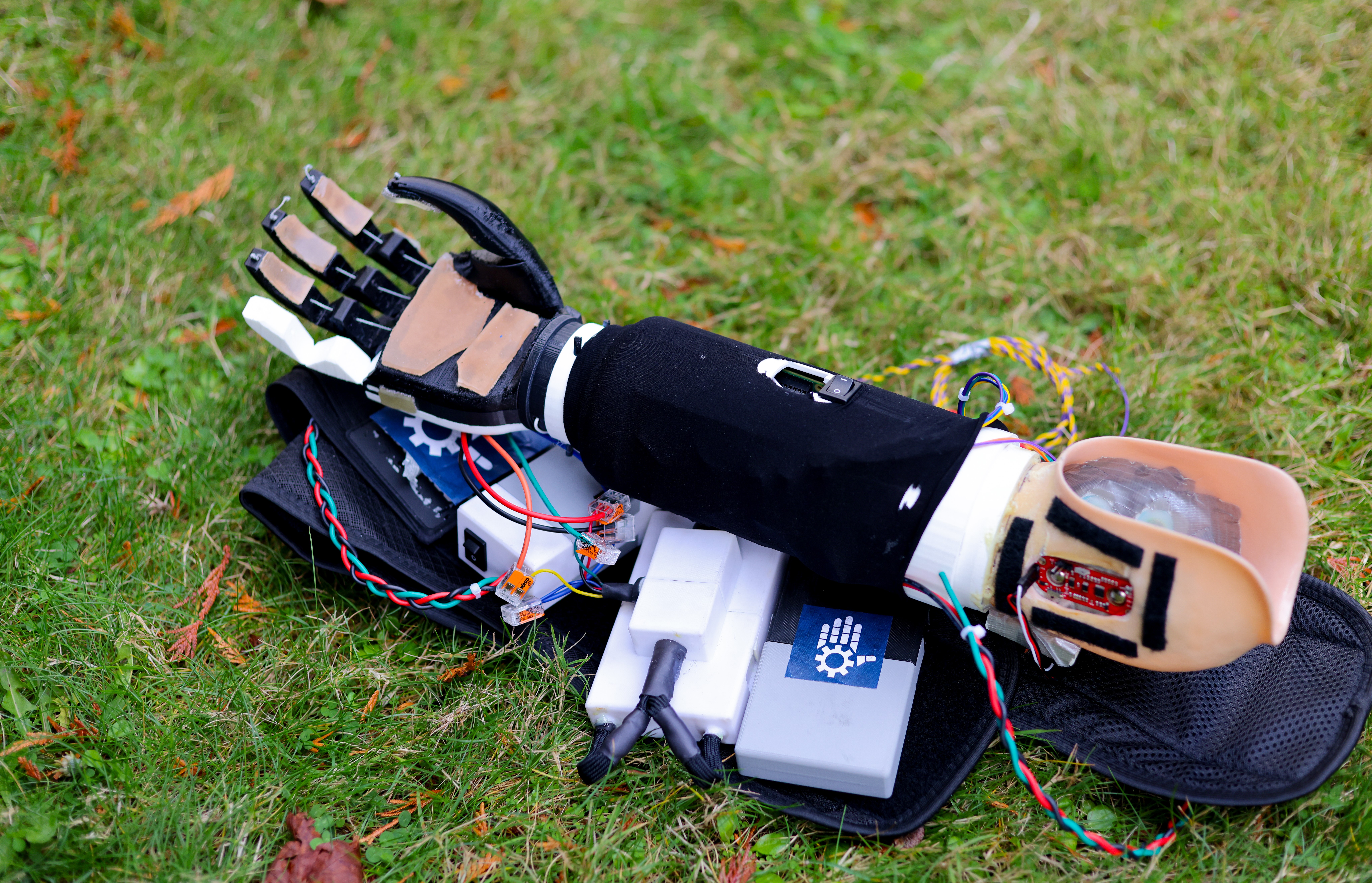
Img 2: A picture of the arm
The BMS was my first project with UBC Bionics. During its development, I gained hands-on experience with soldering (both SMD and through-hole), component selection>, and, most notably, PCB design in Altium, as this was my first complete PCB design and manufacturing endeavor. Here, I aim to share some of the lessons learned and the many challenges I faced throughout this project.
Before moving on, I would like to extend a special thanks to Justin The for being an amazing project partner and doing a lot of research on BMS systems to help catch me up to speed.
1.0 BMS Summary
In general, a BMS is fairly self-explainatory in that it is a system used to manage the battery cell(s) of a greater electronic system, and in essence the BMS must be both safe (provide battery protection) and reliable (be able to manage capacity). To better paint a picture of a BMS, it should include:
- Cell balancing -- to make sure all cells have the same voltage and prevent unwanted overdischarge.
- Overcurrent protection -- to protect the battery against excessive charge or discharge currents
- Temperature sensing -- to monitor the temperature of the board and prevent thermal runaway -> fire
- Overcharge protection -- to prevent the battery from being overcharged which can lead to the afforementioned fire as well as battery degradation
- Overdischarge protection -- to prevent the battery from being discharged below a certain safe level to preserve the battery for prolonged use
1.1 Initial iteration
With these general features defined, we then moved into generally designing the system itself, defining the input and output data of our BMS, but still keeping the system itself as a black box. The system would take in various inputs, such as pack voltage, temperature readings, and the current flowing into or out of the battery pack. It would monitor both the voltage of each individual battery and the overall pack voltage, while measuring current using a shunt resistor or a Hall effect sensor. If an unsafe or undesirable state was detected, a master disconnect feature would terminate charging to ensure safety. The system could also communicate with an external controller, like a Raspberry Pi, to regulate the load more effectively. Outputs of the system would include the State of Charge (SOC), providing an accurate estimation of the remaining battery charge, and the State of Health (SOH), indicating the current capacity compared to the original and showing the degradation over time. Additionally, the system would report any faults or status conditions to maintain safe operation.

Img 3: Rough BMS sketch
2.0 System Specifications
| Property | Design Requirement | Justification |
|---|---|---|
| Performance - Battery State | Device shall deliver updates on the status of each of the LiPo batteries at least every 1 minute | CYBATHLON TecCheck 5.6.1 : CYBATHLON TecCheck requires that the battery state is displayed always when the battery is ON or charging. Status updates of the battery include, but not limited to:
|
| Performance - Battery Charge Time | Device shall reach fully charged from empty state within at most 7 hours | Mean sleep duration for adults is between 7-9 hours . Device can be charged while the user is asleep. |
| Performance - Battery Life | Device shall have a minimum battery life of 80 minutes (1 hour 20 minutes) | Maximum time allocated per CYBATHLON Task is 8 minutes . There are a total of 8 tasks in the competition. Time needed = 8 minutes * 8 tasks * 1.25 (headroom for set up/idle time) = 80 minutes. Realistically, tasks will be broken up to different days but good to overdesign battery life since setup time/idle time between tasks will take a while. |
| Safety - Emergency Stop | Device shall have an easily accessible emergency release/stop to cease power from the batteries | CYBATHLON TecCheck 5.5.2 : “Emergency stops can be easily reached by the pilot, and by a person that is monitoring the device during its application; if not reachable by a person in the vicinity, then there must be a second emergency stop that can be reached easily.” |
| Safety - Batteries | Device shall protect battery from single fault conditions (overdischarge, overcurrent, overcharge) | IEC-60601-1:15.4.3.5 ; Device should protect the battery from single fault conditions to prevent thermal runaway conditions (fire), protecting the user from any first/second/third degree burns. |
| Safety - Excessive Temperatures | Device surface touching patient must not exceed a temperature of 41℃ | IEC-60601-1:11.1.2.2 ; Applied parts that are not intended to supply heat below a surface temperature of 41℃ do not require justification. |
| Safety - ESD Protection | Device shall withstand +2kV, +4kV, and +8kV electrostatic discharges | CYBATHLON TecCheck 5.4.7 , IEC-6100-4-2 : Sufficient electrostatic discharge (ESD) protection to sustain level 1, 2, and 3 Contact & Air Gap voltages. IEC-60601-1-2 (for medical devices) outlines that the device must sustain 2kV, 4kV, 8kV air gap and contact discharges. |
| Safety - EMI | Device shall withstand external EMI or avoid an unsafe state caused by external EMI | CYBATHLON TecCheck 5.4.8 , IEC-60601-1-2 : “Hazards like loss of safety function due to external EMI or an unsafe device state induced by external EMI are prevented.” |
| Technical - Mechanical Dimensions (Master) | Device shall fit within a cylinder of 2.5 inches (diameter) x 4 inches (height) | (Master Board only) Constraints from Mech team, board must fit within a cylinder of 2.5inches in diameter and 4 inches in height corresponding to the forearm of GRASP. |
| Technical - Mechanical Dimensions (Slave) | Device shall fit within a rectangular container of 6 cm (W) x 10 cm (L) x 4 cm (H) | (Slave Board only) Constraints from Mech team, slave board is intended to be mounted on the shoulder with the batteries, to which the container dimensions depend on the batteries’ dimensions. |
| Technical - Weigh | Device weight, including all parts, shall be under 20 kg | IEC-60601-1:9.4.4 ; Portable devices over 20 kg shall be provided with suitable handling devices or accompanying documents on where it can be lifted safely. Generally, wearable devices should not exceed 10% of the body weight which falls around 15-20 pounds for the average male. However, 15-20 pounds on a singular shoulder still sounds extreme so the comfortable weight falls way under, and changes for varying heights and weights. |
3.0 Initial Iteration
Version 1 of the Battery Management System (BMS) involves the use of a Master-Slave topology to connect the batteries to the rest of the GRASP system. Version 1 of the BMS uses 2 boards, the first of which is the master board mounted inside the forearm compartment. The master board contains an STM32 microcontroller to communicate with our slave board, as well as several buck converters to step down the pack voltage to an acceptable level for each electrical subsystem within GRASP. My partner Justin worked on this board.
The other board used for this BMS is the slave board, mounted in a shoulder housing. The main features of the slave board include over fault protection (ex: overcharge, overdischarge), charge balancing, and fuel gauging (State of Charge (SOC) and State of Health (SOH) tracking). These features are carried out by a BQ7791502 battery protection IC as well as a BQ34110 fuel gauge IC both from Texas Instruments. I worked on this board, and most of this page will be discussing the details around it
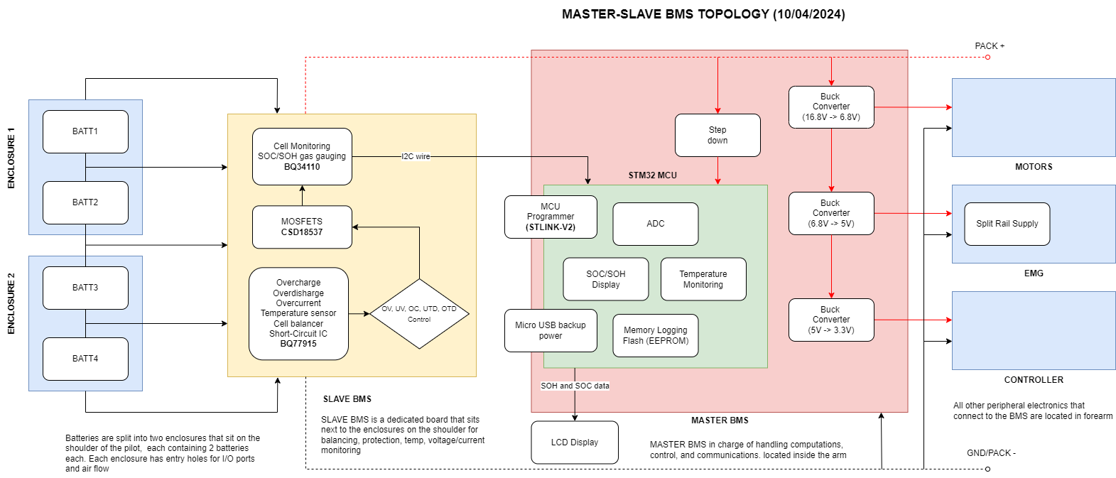
Img 4: BMS architecture
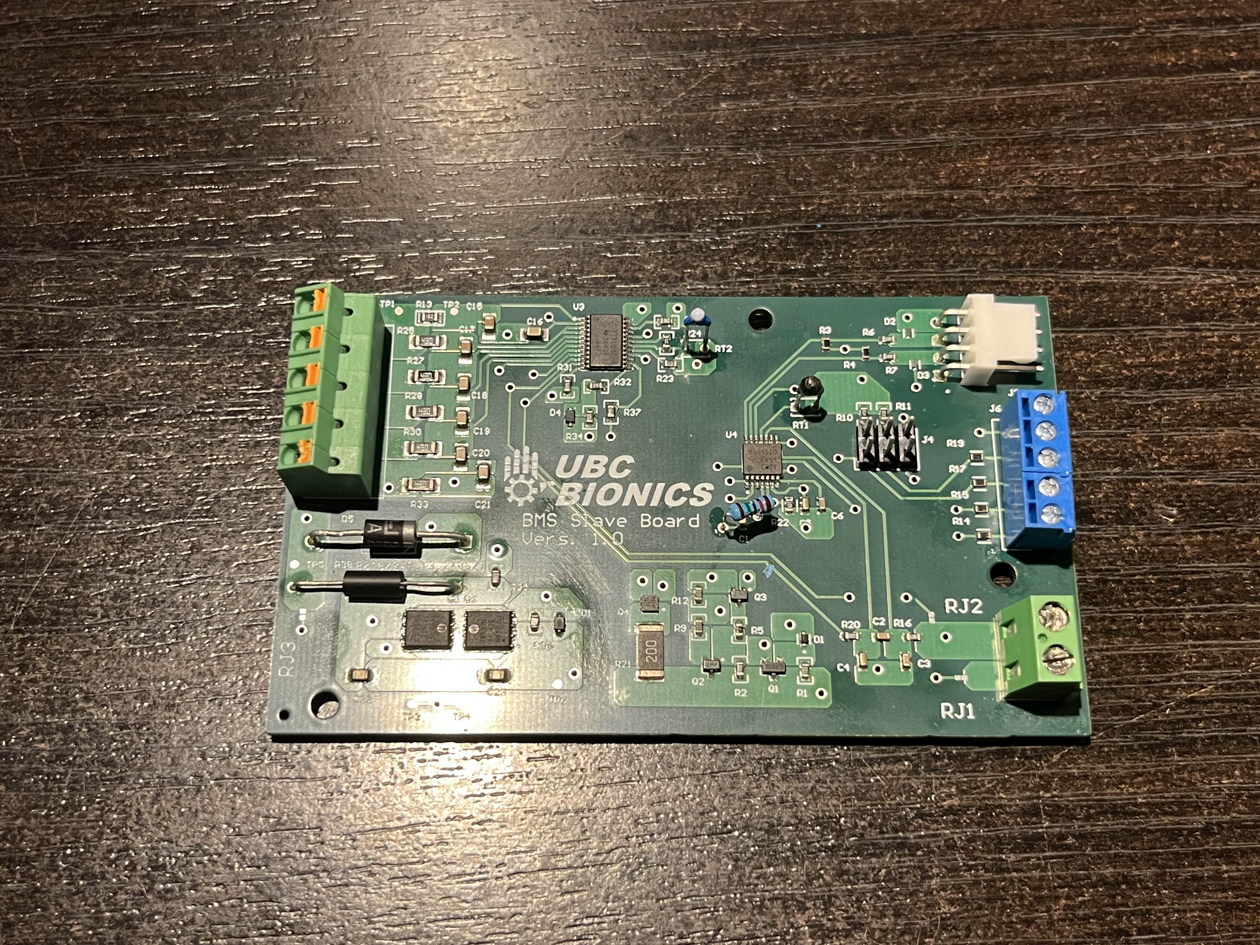
Img 5: The initial iteration of the slave board
Battery Protection (BQ77915)
The battery protection feature of this BMS stems from the use of a BQ7791502 protection IC to prevent the batteries from various over faults.
The BQ77915 is a low-power battery management system (BMS) IC designed to provide a comprehensive suite of voltage, current, temperature protections and smart cell balancing for battery packs without the use of a microcontroller. The BQ77915 IC provides pack protection through integrated CHG and DSG low-side NMOS FET drivers. The IC is also capable of providing passive cell balancing through integrated FETs for cell balancing currents up to 50 mA. Specifically, the BQ77915 protects against the following: overvoltage, undervoltage, overcurrent charge, overcurrent discharge, short circuit discharge, and over/under-temperature while charging and discharging.
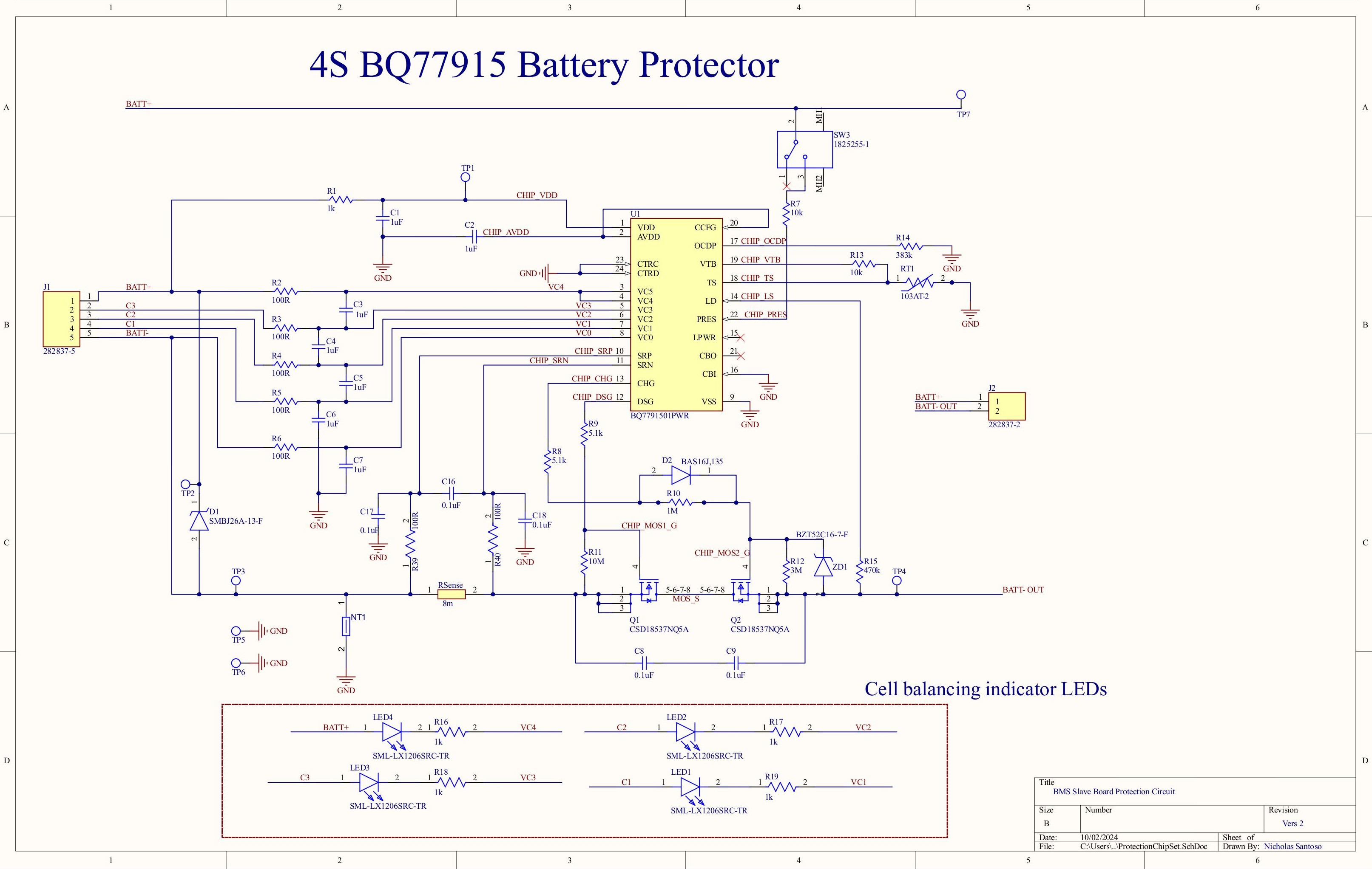
Img 6: Protection circuit schematic
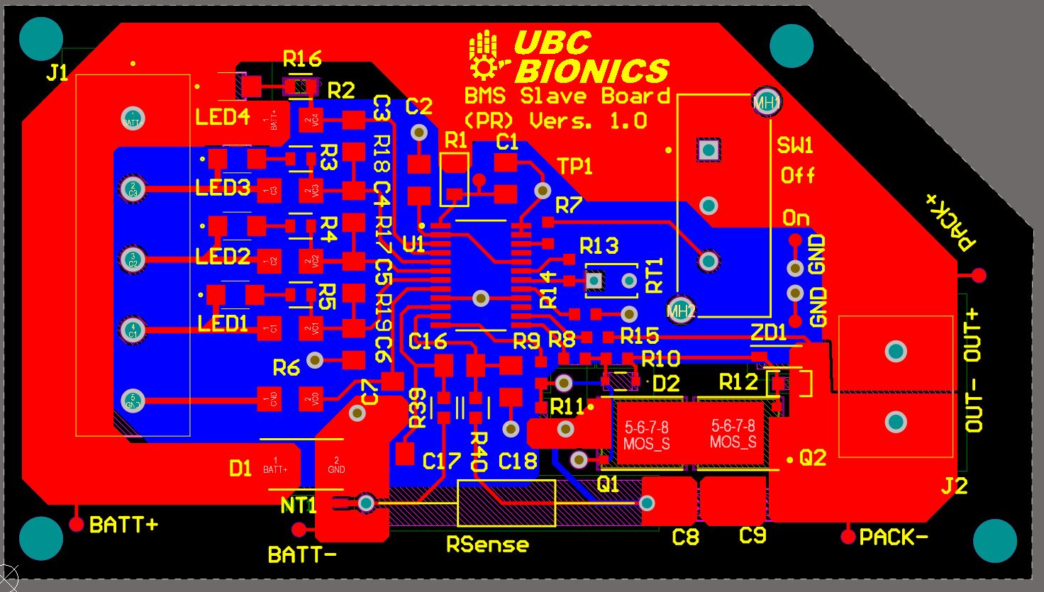
Img 7: Protection board PCB layout
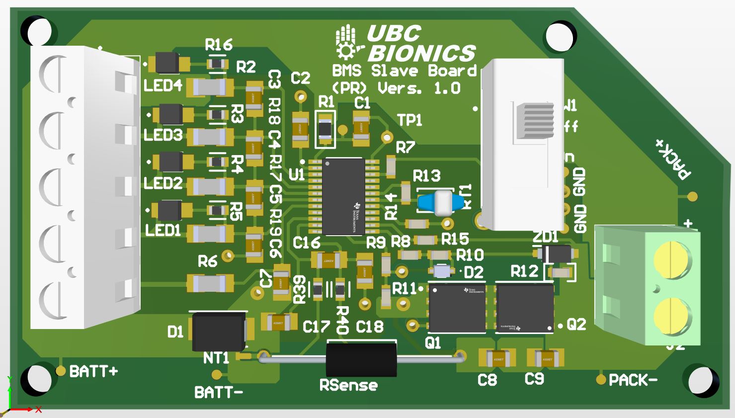
Img 8: 3D render of protection PCB
Fuel Gauging (BQ34110)
The Slave Board of the BMS is responsible for tracking both the state of charge (SOC) and state of health (SOH), primarily through the integrated BQ34110 battery gas gauge. This gauge communicates with the Master Board via the I2C protocol.
The BQ34110 gas gauge leverages Compensated End-of-Discharge Voltage (CEDV) technology to accurately predict battery capacity and performance metrics. It can be queried by a host processor to provide critical cell data, including remaining capacity, full charge capacity, and average current. To monitor battery health, the device's End of Service feature conducts periodic Learning Phases, which involve a controlled discharge of around 1% capacity, alerting the system when the battery nears the end of its usable service life.
Battery current is measured by monitoring the voltage across a series resistor, which is placed in line with the battery pack. This resistor creates a small voltage drop proportional to the current flowing through it. The BQ34110 integrates two ADCs: one dedicated to current measurement and the other for additional parameters such as temperature and voltage. By detecting this voltage drop, the BQ34110 accurately calculates the current flowing into or out of the battery, providing essential data for estimating the State of Charge (SOC). SOC estimation is critical for determining the battery's remaining capacity, as it depends on the cumulative charge or discharge over time.
Communication with the BQ34110 is handled via an I2C interface, through which commands read from and write to the device’s control registers and data flash memory. Cell data is stored in non-volatile flash memory, and accessing specific data requires knowledge of the relevant data flash subclass and offset. Additionally, the BQ34110 provides 32 bytes of user-programmable data flash memory for customizable data storage.
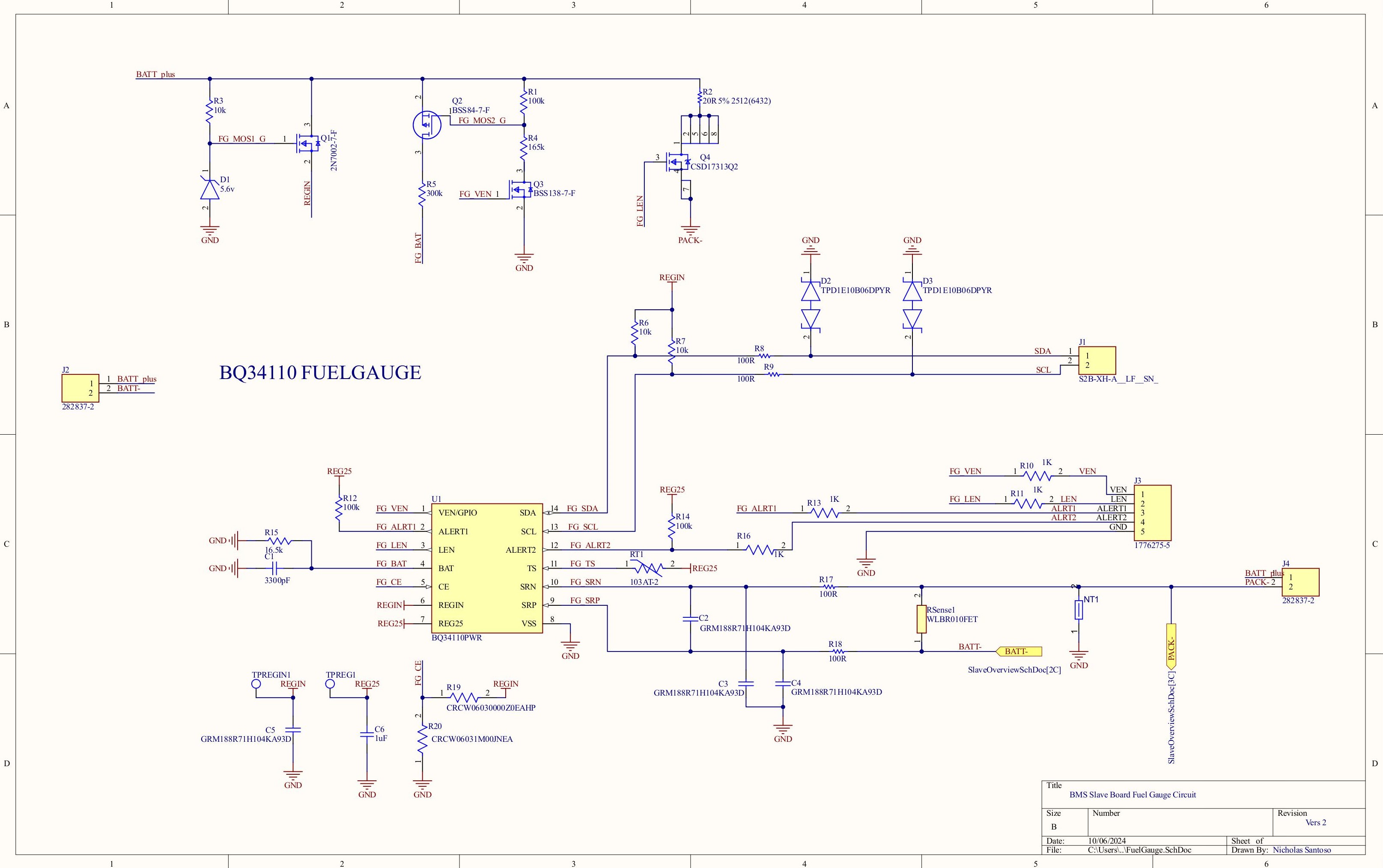
Img 9: Fuel gauge circuit schematic
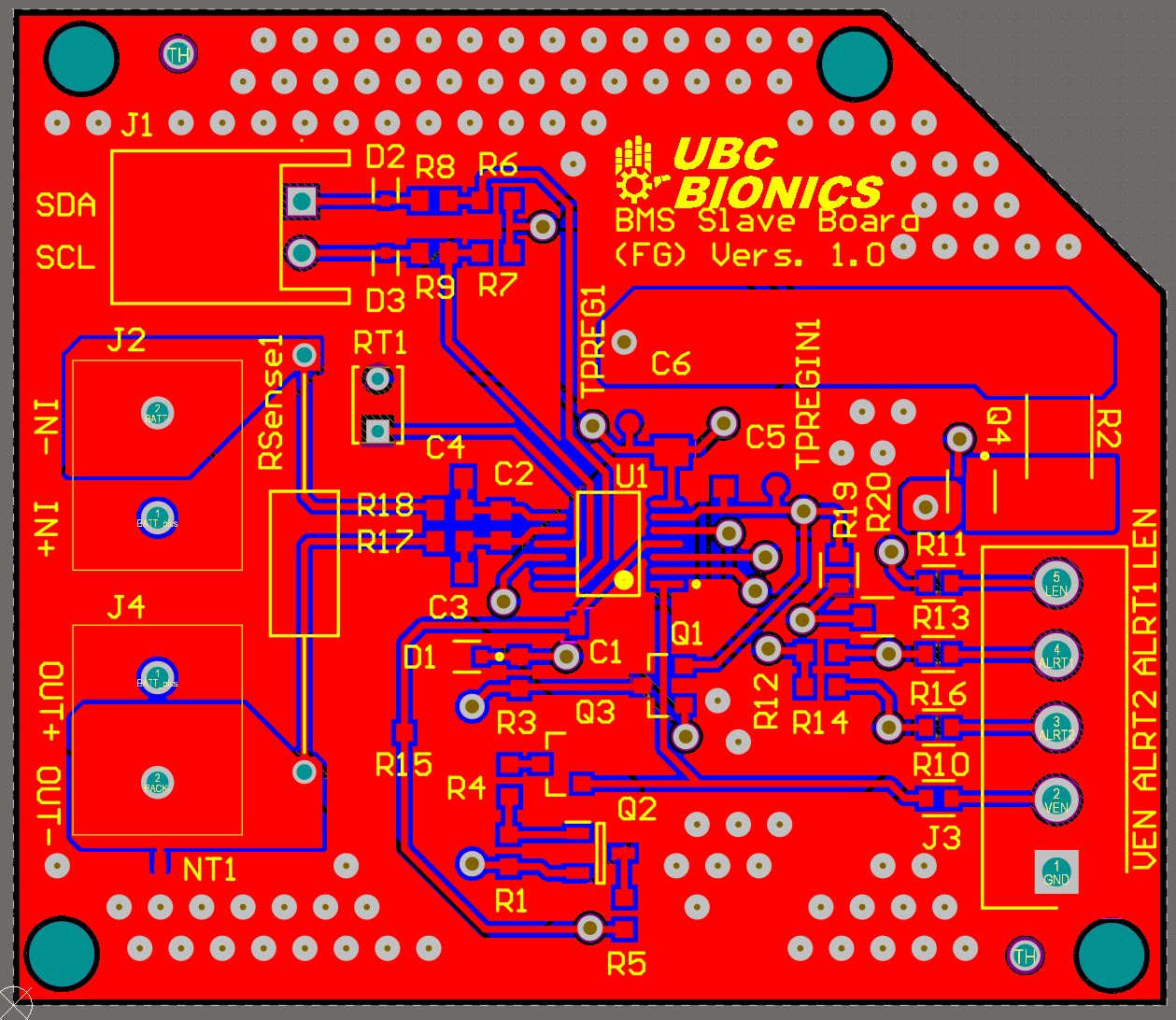
Img 10: Fuel gauge board PCB layout
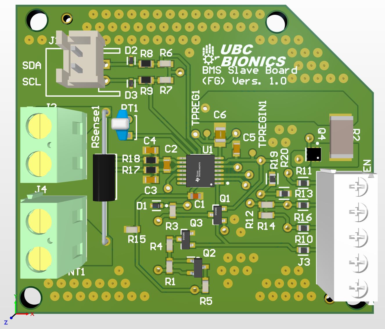
Img 11: 3D render of fuel gauge PCB
Technical Specifications
Battery protection (/cell)
- OV threshold (mV): 4200; Hysteresis (mV): 200
- UV threshold (mV): 2900; Hysteresis (mV): 400
- OW threshold (nA): 100
- OCD threshold (mV): 70
- SCD threshold (mV): 120
- OCC threshold (mV): 70
- OTC temperature (degC): 45; OTD temperature (degC): 65; UTD temperature (degC): -10; UTC temperature (degC): 0
- Cell balancing V_start (V): 3.8
General
- number of series cells: 4
- V_in (max): 25 V
- Overvoltage threshold: 4.2V
- Undervoltage (overdischarge) threshold: 2.9V
3.1 Lessons Learned
So with our first iterations of boards, we both ran into our own issues. However as I mainly worked on the slave, I can only speak in terms of the slave board. When testing it out, I realized I made a pretty big mistake in laying out the board. I realized, a little too late, that I had been accidentally shorting the CHG and DSG MOSFETs by placing vias in series before and after the FETs connected to a ground plane, this allowed current to just flow through the ground plane bypassing the MOSFETs regardless of whether or not there was a fault. This was a careless mistake, as I had the GND symbols on the circuits for both ICs referring to the same net.
To resolve this, I separated the circuits for both ICs into 2 PCBs to essentially make sure that I didn't repeat that mistake, and to test each circuit separately. I also had multiple people review my new boards such that the layout and schematic made sense and were similar enough to their reference. This resulted in the following boards. If I had the time, I would create another iteration where I remerged the 2 circuits into a single board. Addtionally, I would revamp the slave board such that we could use a programmable IC to change cell voltage thresholds to make the system more usable with different batteries, as well as find an IC which performs protection and fuel gauging to further decrease the BMS in size. However, I will leave future work to whomever is working on the BMS this year.
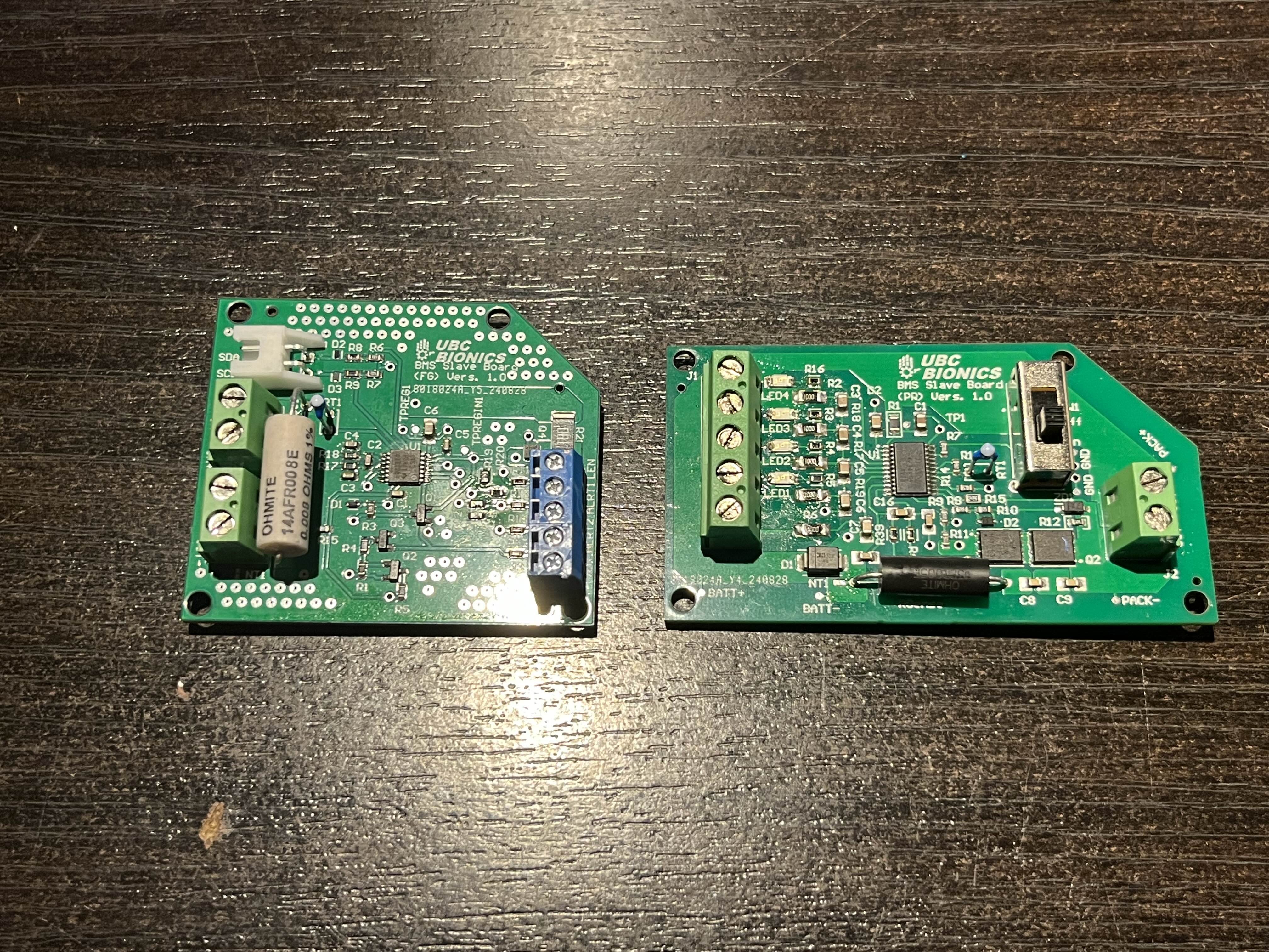
Img 12: 2nd iteration of BMS boards


